Watch our assembly video and study the procedure outlined here to get a good grasp of what’s required.
It is essential that you pull down the trans after setting the backlash and check the gear mesh as shown at the bottom of this page.
Replacing the driven shaft pinion gear
1. Prepare
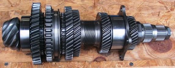
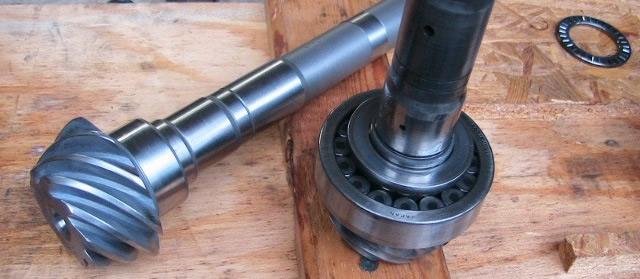
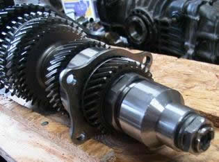
Here is the driven shaft after being pulled from the trans case.
On a front drive Subaru, or any other front drive longitudinal transaxle, the gears would be mounted directly to the pinion shaft. This Subaru setup uses a concentric shaft layout and sends a slender front driveshaft through a hollow driven shaft to drive the front differential.
This shaft has the pinion gear on the end of it and is the one that will be replaced.
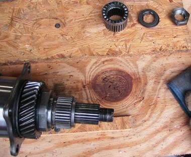
After the 27mm retaining nut, some washers and a bearing are removed from the end of the shaft so it can be pulled out.
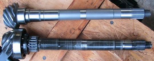
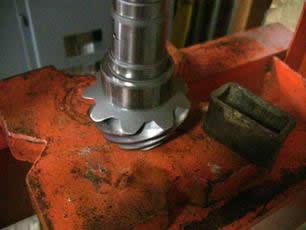
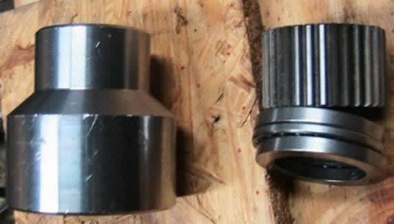
Comparison shot between standard pinion shaft and reversed pinion shaft — note the reversed gear cut on the top one.
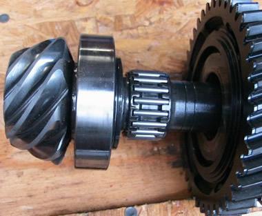
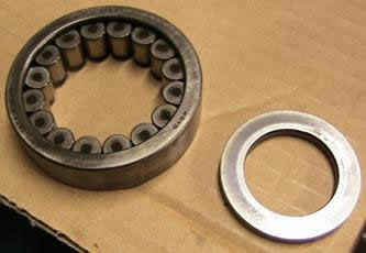
The main bearing that the driven shaft rotates on is mounted to the pinion shaft. If your bearing shows no signs of wear you can re-use it.
The bearing itself is not a press-fit, the collar that holds it on is. The main bearing does not run on its own internal race, it runs directly on the shaft.
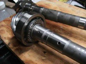
2. Install the collar
Installation of the collar can be done with an arbor and press. This shows a quick arbor made from aluminium pipe. With the main bearing and collar in place, reinstall the smaller surface bearing that allows the vertical surfaces to move against each other.
For 2WD applications, install the Subaspool in place of the splined adaptor, 2 x washers & 1 x surface bearing at the rear of the pinion shaft.
Completed 2WD assembly with Subaspool installed, 27mm retaining nut torque and peened over.
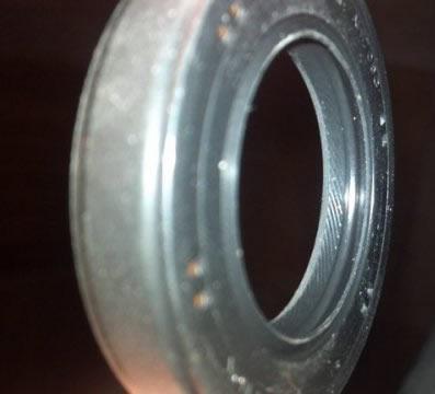
Before re-assembling, you will need to swap the stub axle seals over from left to right. The factory stub axle seals are designed as a one-way seal to effectively keep oil inside the transmission case. You can see this in the image below with the diagonal ribs.
Failing to swap these over will cause the seals to ‘push’ oil out of the transmission case. You can either screw out the bearing cups with seals intact, screwing them back into the other side, or carefully pry the seals out of the cups and install them in the opposite side.
3. If you have the Subaru factory tool available, set the pinion depth.
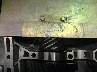
Fit the driven gear assembly to the right hand (modified) gearbox casing and torque the retaining plate up. Zero the pinion depth gauge on a flat surface (such as glass) by loosening the gauge screws, sliding the wedge inbetween the flat surface and gauge indicator so that “0.5” lines up with the mark. Tighten the gauge screws. Fit the Subaru factory tool over the gearbox casing with the dowels. Slide the gauge between the end of the crownwheel gear and the plate. This will show you what thickness of shims you require. This picture shows that the reading is 0.5 and thus will need shims with thickness adding up to 0.5 or just below to bring the pinion depth to zero. A Subarugears Pinion Depth Tool is included in every gear purchase.
Adjust the pinion depth with various shims fitted between the shaft retaining plate and the housing. We re-fitted the two original shims to set the pinion depth to zero.
4. Set the crownwheel mesh into the pinion gear
Set the crownwheel mesh into the pinion gear by adjustment. Assemble both halves of the gearbox, with crownwheel and pinion in place. Screw both side bearing covers in and out as per the factory manual. The pinion shaft should turn easily with a tiny amount of slack when engaging the gears. Once you have met factory specifications, you need to double check the gear mesh with a physical test.
5. Disassemble, assemble, disassemble
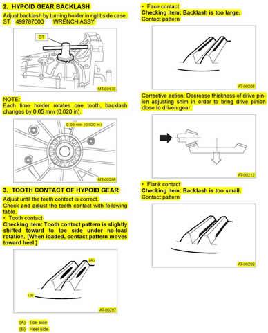
Disassemble the case again and smear bearing blue or yellow gear marking grease onto all surfaces of the pinion bearing. Smear bearing blue onto four teeth on each quarter of the crownwheel gear. Assemble the gearbox again and turn the pinion shaft a number of full rotations in both directions.
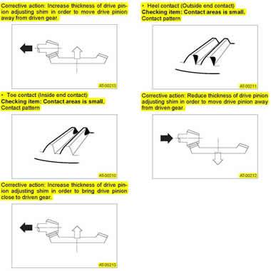
Carefully disassemble the case again and inspect the meshing patterns of the gears, using the factory specifications and illustrations as your guide. Make adjustments as necessary.
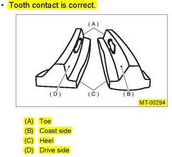
6. Check the meshing pattern
The meshing pattern on each gear should slide along the majority of the gear, engaging and disengaging before the ends where the teeth are weaker. Ensure the depth of gear mesh uses the majority of the tooth but doesn’t bottom out.